CONSTRUCTING FLOOR FRAMING
When the foundation has been laid and the concrete has set up, work can begin on the floor framing. Before starting the floor framing , most carpenters like to have the area outside the foundation backfilled to a rough grade level. this prevents having to jump over a trench and also prevent any injury as a result of falling into the open cavity. It also provides the carpenter with easy access to the building.
TYPES OF FRAMING
Framing methods used in a structure will be determined, to large extent, by the basic design. In addition to this, methods may vary because of conditions found in a certain locality, materials available, and personal experience and preference of the builder.
Some parts of the country, buildings must be built with special resistance to wind and rain. In other parts , earthquakes must be taken into consideration. In cold climates, heavy loads of wet snow may require special roof designs.
Two basic types of framing are;
1. Platform framing, also called western framing.
2. Balloon framing. This type is seldom used any more.
PLATFORM FRAMING
Platform framing starts with a sill fastened to the foundation, a beam in the center of the structure running the length of the building and then the floor joists are laidout on the sill plate and beam with a band board on the ends of the floor joists. Then plywood or another decking material will be used .Therefore giving the carpenters a flat deck to layout the walls and erect them and also provides a good support for a second floor.
BALLOON FRAMING
Balloon framing requires that the studs run from a plate or beam on a foundation all the way to the top plates of the highest point of the building walls, which in the olden days, ran from that beam to the top plates on the second floor and the floors were secured to a board that was let into the studs and a level satisfactory to maintain equal levels around the structure.The seond floor was done in the same manner. Fire blocks were installed into the walls by placing 2 x 4 every four feet and alternating equal distances.
In balloon framing, shrinkage is reduced because the amount of cross sectional lumber is low.
Wood Shrinks across its width but practically no shrinking occurs lengthwise.
Thus the high vertical stability of balloon framing made it adaptable for two story framing , especially if masonary veneer or stucco was to be applied to the outside wall.
GIRDERS AND BEAMS
Joists are the supports of the floor frame. They rest on top of the sill plate, on top of the foundation walls. Usually the span is so great that additional support must be provided and the size and length will be found in the drawings as drawn by the architect. The carpenter need not worry about the load on the beams as that information was figured when the drawings were made.
Girders, also called beams, resting on the foundation walls and on posts or piers, provide the needed support.
Girders may be solid timbers, built up lumber, or steel beams. Sometimes a load bearing partition replaces a girder or beam.
TERMITE SHIELDS
If termites are a problem in your locality, special termite shields should be provided. However with the use of treated materials for the sills this is not always needed.
Termites live in the ground and come to the surface to feed on wood. they may enter through cracks in the foundation or through earthen tubes they build on the foundation walls to reach the wood. However with the proper protection in place it would be hard for them to make access.
INSTALLING SILLS
Normally two types of anchors are used in the laying of the foundation, which may be bolts or straps of metal. These anchors are laid out normally on 4′ O.C. and the sill plate must be laid out to accommodate these anchors.
With the strap type the sill will be positioned on the foundation and the straps nailed either on top or on the sides of the sill plate.
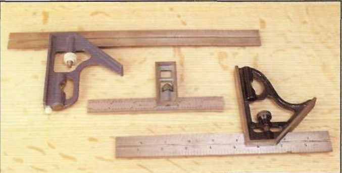
when bolt anchors are used, remove the nut and washer and place the sill plate to the bolts from the inside of the foundation and mark both sides of the bolt on the sill plate with a combination square, then measure back from the outer edge of the foundation to what will be the center of the hole for the bolts. Remember to allow for the thickness of the sheathing at this point. Drill the holes and install the sill plate and continue untill you have completed the perimiter of the foundation.
If a steel beam is used you must attach a piece of sill plate to it at the samw level as the sill plate on the foundation.
Using a solid or built up beam, it will be level with the top of the sill plate.
Having done this you are now ready for joists.
JOISTS
Floor joistas are the framing members that carry the weight of the floor between the sills and girders. In residential construction, they are nominal 2 in. lumber placed on edge. Floor joists are figured to carry on a basis of 50 lb. per sq. ft. ( 10 lb. dead load and 40lb live load).
Joists not only must be strong enough to carry the load that rests on them ; they must also be stiff enough to prevent undue bending or vibration. Building codes usually specify that the deflection (bending downward at the center) must not exceed 1/360th of the span with normal live load. This would equal 1/2″ for a 15′-0″ span.
More will be added to this chapter at a later date.